
Death of Elon Musk’s Hyperloop, The Next is Direct-air Capture (DAC)
Technical promise becomes more informative when it is tested against energy needs, operating conditions and a complete carbon balance. Direct air capture offers a useful example of that discussion.
The short version
- Dilute carbon dioxide requires a different separation task from a concentrated industrial stream.
- Assess air movement, capture-material regeneration, compression, transport and storage together.
- Compare net emissions removed with energy inputs and the full cost boundary.
Separate an interesting idea from its operating case
Highly visible technology ventures can attract interest before their commercial conditions are clear. Comparisons with ventures such as Hyperloop can prompt useful questions about prototype performance, financing and a viable operating system.
That analogy does not determine whether another technology will succeed. For carbon capture, evaluate the particular process, energy supply, scale, site and intended use or storage. Its outlook depends on its own evidence.
Read the comparison as a feasibility question
The comparison with Hyperloop raises a familiar development question: how does a promising demonstration become a system that people can finance, supply and operate? Public attention, a prototype and investment are different forms of evidence. Each can be relevant without resolving the remaining commercial questions. The comparison is useful when it directs attention to a technology's own requirements; it becomes less useful if one venture's difficulties are treated as proof that another technology will have the same outcome.
For direct air capture, those requirements include a suitable capture process, dependable energy, materials supply, carbon handling and a destination for the captured gas. A review can separate what has been demonstrated from what remains an assumption at the proposed scale. This makes room for both technical improvement and practical uncertainty. It also avoids turning a dated discussion about technology ventures into a present-day prediction about the future of an entire field.
Understand where the carbon dioxide starts
Carbon capture and storage connects capture, transport and a suitable storage destination. Carbon dioxide may be separated from an industrial stream or directly from ambient air. Its starting concentration and the required product purity affect the separation task.
Direct air capture treats a very dilute mixture, so substantial quantities of air need contact with capture material. In many sorbent-based systems, the captured carbon dioxide is then released through regeneration that needs heat, electricity or both. Processes differ; assess the specific design.
Separate a physical limit from practical improvement
A separation process works against the tendency of gases to mix. Starting with a dilute carbon-dioxide stream creates a different task from treating a concentrated industrial stream. The thermodynamic minimum is a useful reference under specified conditions, while a practical system has additional requirements for contact, regeneration and handling. A single expression taken without its assumptions cannot describe the complete operating energy or the cost of every capture design.
Innovation can improve materials, heat recovery, contacting equipment and operating arrangements even when a physical limit remains. The meaningful question is how far a design operates from the relevant limit and which part of the practical demand can be improved. Comparing like-for-like concentration, purity and operating conditions keeps that discussion understandable. It avoids both assuming that better technology removes all constraints and assuming that a constraint makes every possible improvement irrelevant.
The source’s separation-work relation
- R
- Gas constant
- T
- Absolute temperature
- P₁ / P₀
- The pressure or partial-pressure ratio used in the stated idealized relation
Follow the energy through the whole chain
Separation has thermodynamic constraints, while real equipment adds energy requirements and losses. Useful questions include how air is moved, how capture material is regenerated and replaced, and how carbon dioxide is conditioned for transport.
Compression or liquefaction, transport and injection add requirements beyond the capture unit. The storage formation and monitoring arrangements also matter. A novel capture material may improve part of the process while leaving other system costs and energy demands relevant.
Examine the energy supply as part of the design
Air movement and capture-material regeneration are important demands. Their relative importance depends on the process. Electricity and heat have different supply arrangements, costs and emissions, so they should be described separately in the assessment. The review can ask when they are required, whether the available supply matches operation, and how the proposed carbon pathway interacts with other uses of energy at the site.
Consider an illustrative comparison between two locations with different heat availability and electricity arrangements. The same capture equipment could have a different overall case at each location, even without a change in its chemistry. A useful analysis would make those assumptions visible before comparing cost or net carbon benefit. It would also include materials replacement and downstream conditioning, because reducing one part of the energy demand may leave another part of the system as the main concern.
Two capture routes and the next carbon decision
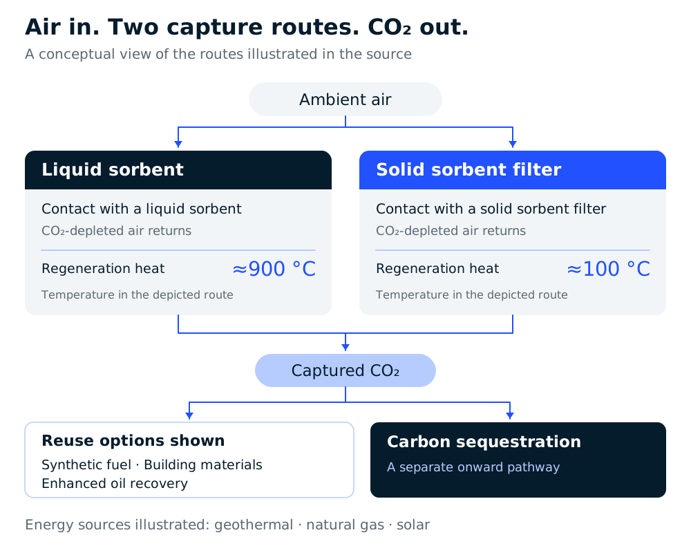 Open figure at full size (opens in a new tab)
Read figure data
| Part of the pathway | Depicted source condition |
|---|---|
| Liquid-sorbent capture | Ambient air contacts a liquid sorbent. |
| Solid-sorbent capture | Ambient air contacts a solid sorbent filter. |
| Liquid-route regeneration | Approximately 900 °C in the depicted route. |
| Solid-route regeneration | Approximately 100 °C in the depicted route. |
| Air leaving capture | CO₂-depleted air returns from each route. |
| Illustrated energy sources | Geothermal, natural gas and solar. |
| Onward captured-CO₂ options | Synthetic fuel, building materials, enhanced oil recovery or carbon sequestration. |
Compare net benefit and practical cost
An amount captured is not automatically the same as an amount removed on a lifecycle basis. Account for emissions associated with the energy and materials used, the chosen boundary and the durability of the storage route. Low-emissions energy can support a stronger balance, but it does not remove the need for assessment.
Compare alternatives using consistent assumptions for feed concentration, purity, energy prices, transport, storage and operating duration. Costs and technology performance change over time and vary by project. The practical question is where a pathway fits alongside emissions reduction and other capture options, rather than whether a single technology can address every source.
Historical capture-cost ranges, with a clear basis
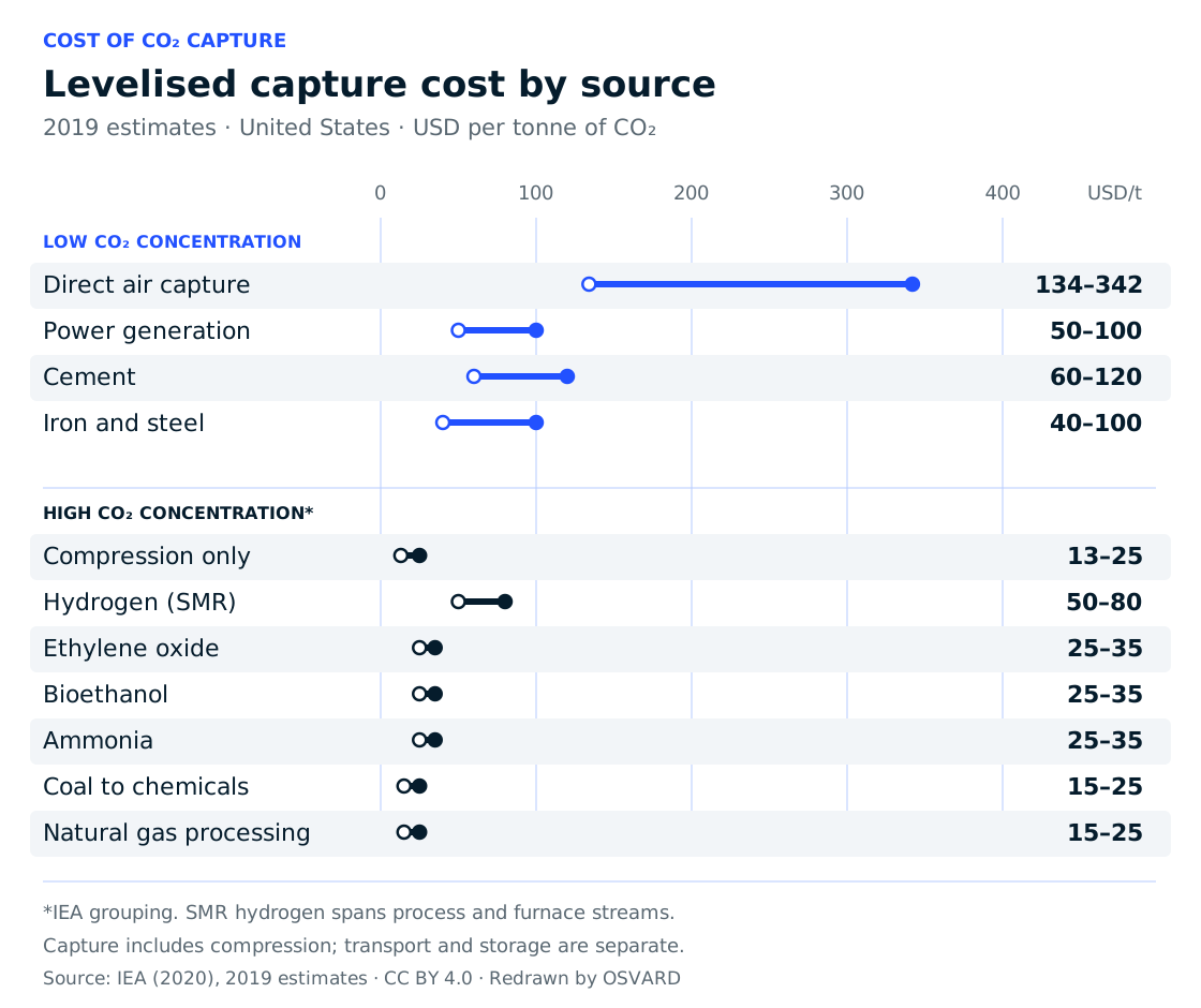 Open figure at full size (opens in a new tab)
Read figure data
| Source | Minimum (USD/t CO₂) | Maximum (USD/t CO₂) |
|---|---|---|
| Direct Air Capture | 134 | 342 |
| Power generation | 50 | 100 |
| Cement | 60 | 120 |
| Iron and steel | 40 | 100 |
| Compression only | 13 | 25 |
| Hydrogen (SMR) | 50 | 80 |
| Ethylene oxide | 25 | 35 |
| Bioethanol | 25 | 35 |
| Ammonia | 25 | 35 |
| Coal to chemicals | 15 | 25 |
| Natural gas processing | 15 | 25 |
Distinguish captured carbon from durable removal
The capture unit is only one part of a removal pathway. The gas may need conditioning, transport and an appropriate storage arrangement, each with its own practical requirements. The quantity captured at a device therefore does not by itself describe a lifecycle carbon result. A reasoned comparison states which associated emissions are included and how the carbon's subsequent destination is treated. Storage durability and monitoring questions belong in the same conversation as capture performance.
The comparison can then distinguish technical performance, net climate benefit and commercial conditions. A favorable result in one does not automatically establish the others. Costs depend on the particular design, energy supply, scale and transport or storage context; historical figures are not universal current prices. DAC can be evaluated alongside direct emissions reduction and point-source capture while recognizing that these approaches answer different questions. The next useful step is to identify which uncertainty most influences the specific proposed pathway.