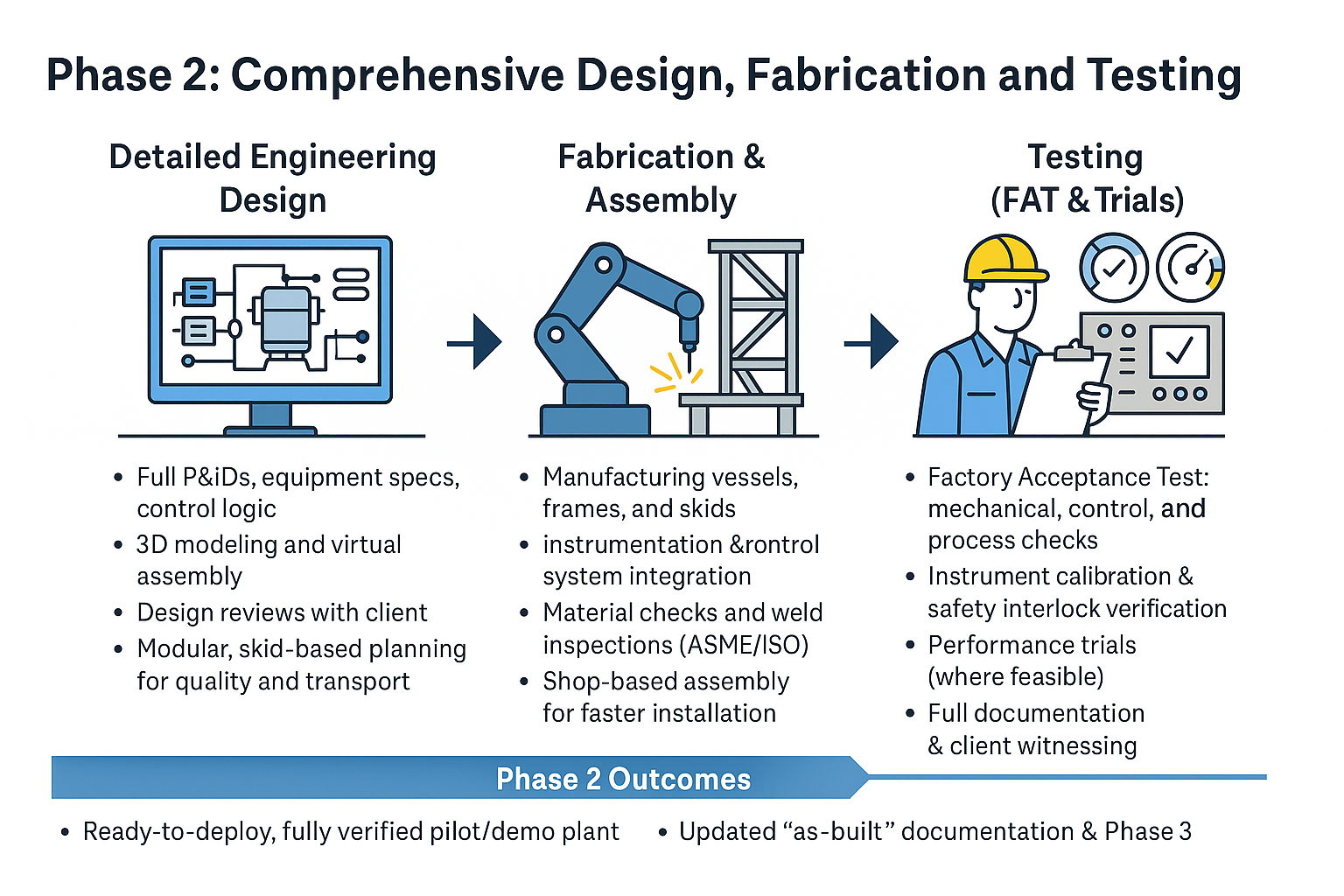
Turning drawings into a living, breathing pilot or demonstration plant
Phase 2 is the make-or-break stretch of any scale-up project. The careful concepts agreed in Phase 1 now pass through an intense engineering crucible: every weld length, PLC tag, and relief-valve orifice is calculated, reviewed, built, and proven. Below is a deep dive into how OSVARD executes this phase so the plant arrives on site ready to run—not ready to rework.
From PFD to bullet-proof P&ID
Instrumentation detail. Each tag gets a calibrated range, material compatibility check, and installation orientation. Even small pilot valves are sized with ISA guidelines so controller tuning later is painless.
Mechanical integrity. Shell‐thickness calculations follow ASME VIII or EN 13445, including wind/earthquake loads; nozzle loads are checked against WRC 537 to ensure piping strain won’t crack a flange six months in.
Control philosophy. OSVARD writes cause-and-effect charts, ESD matrices, and interlock logic before a single line of PLC code is drafted. This freezes safety intent early and avoids “feature creep” later.
3-D CAD and clash detection
A full SolidWorks®/Plant 3D model is built, including cable trays and service corridors. Virtual walk-throughs catch ergonomic issues—operator can’t reach that sample valve, handrail blocks lifting eye—while changes cost nothing more than a mouse-click.
Modularisation strategy
Whenever transport permits, we pack equipment on skids no wider than 2.4 m (standard container width). Shop-built modules:
improve weld quality (controlled environment)
slash field hours (fewer hot-work permits)
let functional checks run before shipping.
Vendor kick-off and quality plans
OSVARD issues a Manufacturing Quality Plan (MQP) that lists hold-points for material certificates, weld procedure qualification, PMI, hydrotest pressures, and paint DFT checks. Nothing ships without a signed inspection release note.
Code welding & non-destructive examination
WPS/PQR approval ensures the welder, filler metal, and heat input meet code toughness requirements.
100 % radiography on Category A seams for pressure vessels over 50 bar; dye-penetrant or ultrasonic on others according to risk ranking.
Hydrotests at 1.3 × design pressure catch early leaks; we often run a nitrogen pressure hold afterwards for sensitive internals.
Control-panel integration
Panels are assembled in a clean electrical shop. All I/O channels undergo loop checks—voltage range, signal integrity, and fail-safe direction—long before the skid sees process fluids.
FAT is more than a box-ticking exercise; it is the first opportunity for operators and engineers to treat the unit as if it were already on their site.
Mechanical run-in – Pumps turn with water; vibration and seal temperatures are logged for baseline data.
Safety-instrumented function tests – Simulated pressure trips, level highs, or flow-fail signals validate every shutdown path.
Control-loop checkout – PID gains are rough-tuned, interlocks verified, alarms rationalised.
Process functionality demo – Where chemicals are safe to handle, OSVARD performs a short “mini-campaign” so heat-transfer, residence-time, or filtration rates can be proven on real materials.
Each punch-list item is cleared, and the client signs a detailed FAT dossier—complete with calibration certs, as-built P&IDs, wiring diagrams, and material traceability records.
For catalytic or bio-process rigs, OSVARD offers extended shop trials—24 h to several days—using genuine feeds. Benefits include:
early catalyst light-off and deactivation data,
confirmation that heat-duty predictions match reality,
operator training with the actual control screens.
These runs often reveal subtle tuning tweaks that make Phase 3 start-up markedly smoother.
Stage-gate reviews tie payment milestones to tangible deliverables—approved drawings, finished modules, successful FAT—so budgets stay predictable.
Long-lead procurement tracking flags items such as exotic-alloy agitators or SIL-rated transmitters months in advance.
Risk registers are live documents: if a weld repair pushes schedule, shipping dates and site-prep timelines are auto-re-baselined.
As-built 3-D model and intelligent P&IDs (with tag-linked datasheets)
Material data book – MTRs, welding maps, NDE reports, paint certs
Control system back-ups – PLC/DCS programs, HMI graphics, and alarm set-points
FAT & performance-test report – summary of procedures, raw data, deviations, and resolutions
Shipping release – packing lists, centre-of-gravity sheets, and lifting drawings for each module
With every bolt torqued and every sensor calibrated, the plant is ready for Phase 3—delivery, on-site setup, and commissioning—without hidden surprises.
“Measure twice, weld once, test thrice: that’s how prototypes become production assets.”
Need your pilot or demo plant built fast and fault-free? OSVARD’s Phase 2 execution framework delivers workshop-tested hardware that performs on day one—so your innovations can sprint toward commercial reality.